CRITICAL FLOW NOZZLE
Bulletin 101
1. DESCRIPTION
The Flow-Dyne "Critical Flow Nozzles" are converging-diverging nozzles
designed for the accurate measurement and control of all gaseous flow rates
within the range of 0.05 pounds per minute (0.66 SCFM) up. The internal
configuration of the Flow Meter consists of a Bell Mouth converging inlet
section, a minimum area throat followed by a conical diverging diffuser section
as shown below.
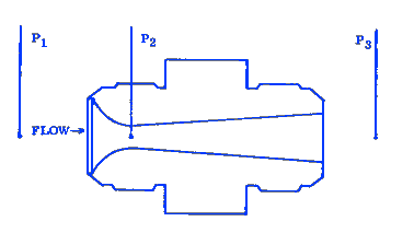
Operating on the principle of critical flow, only the inlet pressure and temperature measurements are needed to determine the flow rate. The flow rate varies linearly with the upstream pressure and is not affected by downstream pressure fluctuation or changes by virtue of sonic velocity existing at the throat. The diffuser provides efficient recovery allowing critical flow to be maintained at inlet to exit pressure ratios (Pl/P3) as low as 1.2. There are no moving parts to affect reliability.
2. APPLICATION:
- Flow standards for calibration of other meters with all gases (air N2, 02, He, H2, etc.) in the range of 0.05 pounds per minute (0.66 SCFM) to no upper limit.
- Working meters in Development, Qualification and Inspection tests.
- Flow Capacity and pressure drop tests on valves, ducts, electronic package cooling, heat exchangers.
- Wind tunnel calibration.
- Flow Limiting venturis for control of gaseous flows.
- Test stands and OEM products.
- Measurement of airplane cabin leakage flows.
3. PRINCIPLE OF OPERATION:
As the gas flows through the converging section of the nozzle the inlet
pressure is converted to velocity, reaching a maximum value at the throat. The
diverging section then slows the gas down by reconverting the velocity back to
approximately its original pressure. When the inlet pressure P1
is in the range of 100% to 120% of the downstream pressure P3
the converging diverging nozzle if equipped with a pressure tap at the throat P2
is readily recognized as a venturi flow meter. This type of meter covering all
flow rates from 0.05 lb./min. is described in Flow-Dyne's Bulletin 201. Ideally
all inlet pressures greater than 120% of the downstream pressure will produce a
flow condition in the nozzle which is known in various fields as critical flow,
sonic flow, choked flow, and limited flow-thus Flow-Dyne's Critical Flow Nozzle.
Critical flow is characterized by the gas velocity in the nozzle throat being precisely equal to the speed of sound. Under these conditions, a fixed pressure ratio exists between the inlet P1 and throat P2 for all inlet pressures, thus eliminating the need for a throat pressure tap. By virtue of the sonic velocity at the throat, downstream pressure changes cannot affect the upstream pressure and the flow rate becomes dependent upon the upstream pressure and temperature only.
The flow equation for critical flow is:
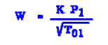
Where:
W = Weight flow rate
P1 = Nozzle inlet pressure (absolute)
T0l = Nozzle inlet temperature (absolute)
K = Calibration coefficient supplied with each nozzle includes velocity of approach and discharge coefficient resulting from calibration.
4. DESIGN FEATURES AND SPECIFICATIONS:
Design Standard:
The internal configuration of these nozzles is designed to optimize the
theoretical prediction of discharge coefficient. External design is unlimited
and can be tailored to fit any tubing, piping or bulkhead mounting system.
Although there are several Standard designs available, such as the AN union
pictured above, the purchaser may specify any type of fitting and delivery date
will not normally be affected.
Material:
Standard Nozzles are manufactured from type 303 stainless steel for
durability and corrosion resistance.
Type of Connection:
Virtually any type of end connections can be supplied on Flow-Dyne's
critical flow nozzles. A few of the
typical
connections are listed below
Installation:
The critical flow nozzle mounts directly in the line and can be installed
in any attitude without affecting performance. It is recommended that the
approach tube containing the inlet pressure and temperature tap, be
approximately 10 diameters in length. The static pressure tap should be located
2 diameters and the total temperature pickup 6 diameters upstream of the meter
in the tube. Where valves and bends which might seriously affect the flow
condition are present upstream, an approach tube with flow straighteners and
instrument taps can be provided.
Instrumentation:
The critical flow nozzle requires only two measurements to calculate the
mass rate of flow. They are
A third measurement of nozzle exit pressure should be observed, though it
need not be recorded. This is to insure that a critical pressure ratio between
the inlet and exit of 1.2 or greater exists.
Accuracy:
Calibrated critical flow nozzles are supplied with NIST traceable
certification and will produce mass flow data within an accuracy tolerance of
less than 1.0%. A complete calibration curve is supplied with each calibrated
nozzle. Uncalibrated nozzles are supplied with calculated performance curves
based on actual measured throat diameters, calculated approach velocities, and
ASME discharge coefficients. They can be expected to yield 2.0% data or better.
Head Loss:
It is necessary that the pressure ratio between the upstream section and
the throat (Pl/P2) be approximately
1.9 in order to accomplish critical flow conditions. However, the diverging
section will recover a portion of this head loss. Due to manufacturing and
interchangeability considerations, each nozzle of a set is the same overall
length. Thus, for different throat diameters, the length of the diverging
section is compromised slightly and optimum recovery is not realized on all
nozzles of a set. Overall pressure ratio (inlet to exit, Pl/P3)
for any set could range from 1.2 to 1.5. For special applications where head
loss is a limiting factor, special nozzles can be readily supplied.
The minimum overall pressure ratio necessary to choke the nozzle will be supplied with each nozzle.
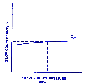
5. DATA REDUCTION:
To compute the flow rate through the nozzle from the measured data of
upstream pressure and temperature, and the Flow Coefficient curve supplied with
each nozzle, proceed as follows:
- Enter the Flow Coefficient curve (sample below) at your operating pressure and extract a flow coefficient, K.
- Then, using your measured data and the proper K, you may compute the flowrate through the nozzle with the following equation:
Where:
W = Flow Rate in lb./min.
P1 = Nozzle, upstream absolute static pressure in psia
T01, = Nozzle upstream total temperature in degrees Rankine (460 + deg F)
K = Flow coefficient obtained from the curve supplied with each nozzle.
(This curve is valid over a wide range of temperatures and only under extreme conditions is it necessary to supply more than one temperature line on the flow curve).
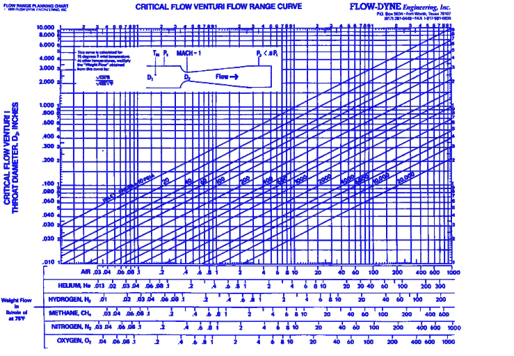
6. NOZZLE SIZE SELECTION:
In selecting a nozzle size for your application, consult the Nozzle Flow Range Curve on the chart below. On this curve AIR Mass Flow W, is plotted Vs. Nozzle Throat diameter with nozzle upstream pressure as a parameter. For example, nozzle number NXXO250, which has an O.25 inch throat diameter, would meter 1.69 to 6.77 pounds per minute of air by varying the inlet pressure from 25 to 100 psia. The range of each nozzle may be increased in direct proportion to the inlet pressure which is available from your system. Thus if 300 psia is available, this same nozzle would meter up to 20.31 PPM of air. Mass flow scales for Hydrogen, Oxygen and Helium gas are also shown on the curve.For example the nozzle described above would meter up to 7.8 PPM of Helium at 300 psia nozzle inlet pressure.
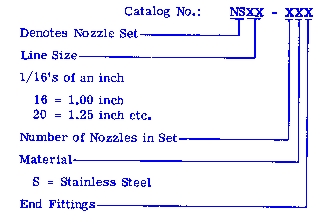
7. HOW TO ORDER OR REQUEST FURTHER INFORMATION:
If you have selected your nozzle sizes by following the instructions in article 6, then you may order or request price information by the following Catalog Numbers:NOZZLE SETS
Note:
See Catalog for further description of Nozzle Set.
A - AN Aircraft type Flared tube
V - "V" Flange Ref: Aeroquip Marman P/N 56400
C - Conoseal Flanges Ref: Aeroquip Marman P/N 51132 or 51133 for Line Size 1.00 inch: P/N 54971 for Line Size 4l.00 inch.
PF - Pipe Flange (Sandwich)
PT - Pipe Thread (Male)Individual Nozzles